
The Saugus Pot and the Birth of the Foundry Industry in Colonial America
Click here to read the article and see all the figures in the October digital edition.
In 1642, a small and fledgling industrial enterprise called Hammersmith (now the Saugus Iron Works National Historic Site) cast what has come to be known as the Saugus Pot (Figure 1). To the casual observer this pot might be viewed as rather insignificant in the scope of a developing nation. But to the informed citizen, the casting represents freedom and independence. In the overall scheme of events, the small, fat pot may have greater significance to America than even the Liberty Bell. The pot is a testament to American creativity, ingenuity and commitment. Many Americans who visit the Saugus Iron Works come away with the feeling that this beautifully reconstructed landmark may well be where the first battle for independence from Britain was fought and won. The foundry industry is fundamental and integral to the country’s manufacturing base and it will always enjoy the luxury of that status.
Inspired by the Saugus Pot and what it represents, the authors set out to reproduce the piece using today’s metalcasting techniques.
Saugus Pot and the Birth of a Nation
Life for early settlers in America was harsh. To build sustainable settlements that could provide for the colonists and protect them against the harsh wilderness, they needed hardware. America had vast amounts of forests that could supply the chief building material of the time: lumber. On the other hand, metal goods such as nails, horseshoes and cookware had to be imported from Great Britain at huge expense. For New England to truly thrive, metal-producing facilities needed to be established in America. In the vast resources of the new continent, colonists saw an opportunity to produce the iron goods they needed to sustain economic growth. These resources also provided an opportunity to spur New England’s economy—then in a depression—through the export of raw iron and finished goods.
At about this time in the early to mid-1600s, England’s forests used to produce the charcoal necessary for iron production had become so depleted the British began looking to America to provide the pig iron used to make the iron goods that drove the growth of Great Britain’s population and economy. Thus, in 1641 John Winthrop the Younger left Massachusetts Bay Colony for England, seeking funds to establish the first large-scale iron-producing operation in America. Under Winthrop’s direction, The Company of Undertakers of the Iron Works in New England was founded with Puritan capital.
In the 1600s, blast furnace iron production required ore, flux, charcoal, waterpower and skilled labor. A location near the town of Lynn, Massachusetts, on the Saugus River met all the key criteria. The location on the river was navigable and had a precipitous drop that could be used to power the furnace blast bellows and mills. The surrounding forest provided charcoal while nearby bogs supplied ore. Gabbro, an igneous rock, was found to be a suitable flux and was mined close to the selected site. Skilled labor in the form of a clerk, a miner, a founder, a finer and a smith was imported from Britain.
The iron works smelted bog iron in the blast furnace, creating high carbon, high silicon iron and pig. This pig was heated and worked by drop hammers into wrought iron. The wrought iron was worked into bar and strip and became the source of forgings and forging stock for blacksmiths. In this regard, the Saugus Ironworks was thought of as a user and producer of both primary and secondary metals. But the casting of pots, fire backs, and other goods made the iron works an end producer and gave it a highly significant place in history.
Saugus Iron Works operated until sometime between 1676 and 1678. It generated a modest profit, but not nearly as much as the shareholders demanded and all operations ceased. The unemployed ironworkers spread out across New England plying their trade in new locations, helping to spawn more metalworking plants across the colonies and laying the foundation for the foundry industry in America. It provided an economic base for the colonies and ensured their self-sufficiency, which soon became a source of tension between New England and Great Britain.
Ironworking and Rebellion
The 1750 Iron Act made it illegal for colonists to build rolling or slitting mills, trip hammers and furnaces used to produce nails, wrought iron and steel. The Iron Act also discouraged the production of iron goods that had been made with this equipment in the colonies. The law meant that colonists would have to purchase finished iron goods at a much higher cost from Great Britain.
To colonial foundrymen, the Iron Act of 1750 was an excessively restrictive law imposed on American manufacturers by King George and the British Parliament that would have severely limited the American colonies’ ability to meet their own needs for finished goods.
Fortunately for the colonists, local governments were happy to collude with iron masters to flout the law. Nevertheless, this increased tensions between colonists and the British. The Stamp Act of 1765, imposing a tax payable in British currency on all printed goods without colonial consent, only increased tensions between colonists and the British. The passing of the infamous Tea Act of 1773 was the final straw that brought seven foundrymen to the signing of the Declaration of Independence on July 4, 1776.
The ability of colonists to provide for themselves, symbolized by the Saugus Pot, contributed to their unrest when that ability was stripped away by British law, ultimately leading to independence for the 13 American colonies.
Casting the Original
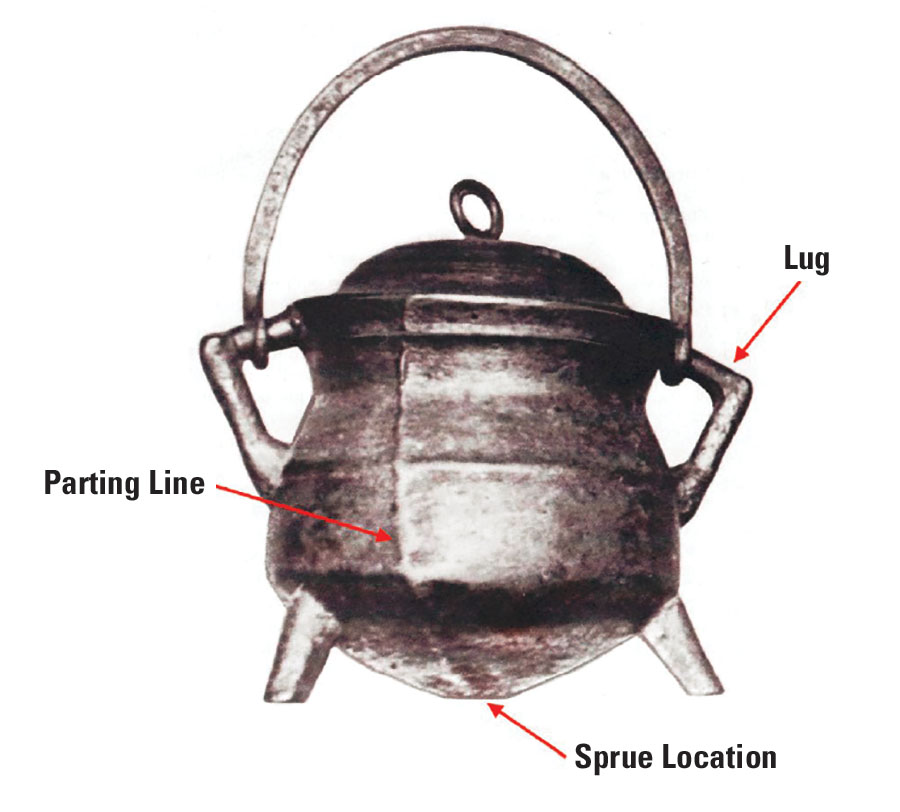
The making of the Saugus Pot, ostensibly the first utilitarian iron casting in America, is credited to Joseph Jenckes Sr., a cutler and foundryman. No record remains of the technique Jenckes used to produce the pot. However, features of the Saugus Pot itself and period writings give clues about the design and production of the artifact.
The sweeping marks on the surface of the pot suggest that loam molding was used. The mold was likely complex, consisting of three layers of spherical loam separated by thin layers of parting compound. Consistency of each layer was obtained by rotating the loam on an iron and wood core bar mounted horizontally on the molding bench and using a different sized molding board attached to the bench in the same location for each layer.
The core may have been formed on a rope base wrapped around the core bar. Once the three layers of loam were produced, the mold was dried under low heat. The molder then most likely cut away the third layer to reveal and discard the second layer of loam, forming the basic mold cavity. The core bar was then pulled from the core and the wound rope removed. The remaining holes on the core were then patched.
Loam molds were created for the three legs and two lugs using wooden patterns. Holes were made in the outer layer of the pot mold to attach the lug and leg molds. The lugs were applied 180 degrees apart, while the legs were attached approximately 120 degrees apart, with two legs on one half of the mold and the third leg on the other. The outer loam halves were assembled around the core and the seam repaired. The mold, with the core inside, was dried again and placed upside down in a hole in the casting floor, then covered with sand. The pot was likely gated through a conical loam riser attached to the mold base.
Recreating the Saugus Pot
The project to recreate the Saugus Pot began with a trip to the Lynn Public Library in Massachusetts where the original artifact is kept.
Examining and holding the actual artifact provided the opportunity to vicariously see the molder’s planning, thinking and decision-making regarding mold preparation and rigging techniques.
After examination, it became very clear today’s casting technology would lead the authors to go about molding and pouring the pot and lid using quite different methodologies than the original.
The first decision regarding mold cavity design was to create a solid model and split the pot directly through the opposing side handles, or lugs, allowing for full positive draft of the pot body in contrast to the original parting line location, which did not allow for integral molding of the lugs. A vertical seam mold was also decided upon, with the sprue entering the underside of the casting cavity. Once a solid model was created, it was split in half through the lugs, and a 0.25-in.-thick matchplate pattern produced using laminated object manufacturing (LOM) with alignment pins was built into the design (Figure 2).
With the attached legs spaced 120 degrees apart and integrally attached to the solid model, the pattern as built would not allow for pattern/mold separation. Some technique had to be created for functional molding, leg cavity creation and leg pattern extraction. Examination of the original artifact seemed to indicate that leg cavities were cut by some sort of trowel or cutting tool. Leg shape irregularity and imperfect placement reinforced this thinking. The legs on the solid model were virtually perfect in both geometric shape and position, but as attached they would prevent pattern removal from the sand mold. The forgiving nature of the nobake process eliminated the problems associated with tight packing. AFS GFN 100 rounded grain silica and nobake molding opened some opportunities for molding practice that lent itself well to leg formation detail. But still, leg protrusion prevented mold/pattern separation.
After the solid model was built, 0.166-in. holes were drilled vertically through each leg while attached to the pot body to a depth of about 0.75 in. The drilled holes served as precise locations for each leg and served as a locational clearance hole for a #8-32 threaded fastener. A jeweler’s saw producing a tiny kerf was used to cut each leg away from the pot body following the curved contour of the body itself. Legs were numbered to keep location and registration as perfect as possible.
Metal inserts were installed in the pot body at this time so each leg could be tightened with perfect positioning at the location from which it originally came. Three aluminum pins were drilled and tapped, and #8-32 threaded brass studs were permanently inserted into each pin. Brass alignment sleeves with a 0.252 in. inside diameter were installed directly into the side of the wooden flask frame precisely over each leg location to accommodate a moderate (RC4) clearance hole for the 0.25 in. aluminum hold-down pin. Finally, the flask on each side could be filled with nobake sand, and after set-up, the aluminum hold-down pins could be removed. The mold could be separated from the matchplate, and—once separated—the legs could be pushed out of the sand mold leaving perfect leg cavities for the molten metal to fill. Also, the holes in the mold left by the hold-down pins would function as open vents, further aiding appropriate mold filling. Figure 3 shows the matchplate pattern held in the taper-sided flask with a single leg and hold-down pin in place.
Clearance holes were drilled in each leg for a #8-32 threaded fastener. Aluminum rods (0.25 in. O.D.) were end-tapped #8-32, and brass machine screws were wound into the aluminum rods. Inserts were threaded into the locating holes left in the solid pot pattern with #8-32 internal threads. Directly above each leg location, 0.252 in. brass sleeves were permanently set in the side of the flask (Figure 4).
A rapid sand mixer was calibrated to add 1% total resin to the molding material—an AFS GFN 100 rounded silica. One mold half was filled, packed moderately, and struck off. After a set-up time of about eight minutes, the leg pins were removed, the sand mold was separated from the pattern, and after careful examination, the technique was determined to have worked perfectly. The pins were used to push the leg sections out of the sand mold, revealing a good external mold cavity.
In designing the pot pattern, provisions had to be made for careful positioning of the core. A tapered pattern extension was added to the matchplate to allow the core to sit perfectly centered in the mold cavity. Core adhesive helped secure the core during pouring.
A corebox was designed using the same solid modeling technique as the matchplate. Core size and shape established wall thickness and precise location for the finished casting. Figure 5 shows the LOM core box and the solid, nobake core.
The core and mold, coated with Velvacoat A-10 and assembled with mold/core adhesive, poured perfectly. The solid core, however, used a significant amount of sand and resin and produced some gas defects inside the finished casting.
Fortunately, while the authors were attending an AFS-Texas Chapter meeting in Houston, one of the chapter members, Ted Keen, who owns and operates Superior Pattern Works Inc., overheard a discussion about the core gas problem with the Saugus Pot project. He suggested creating a shell core. The authors sent him drawings of the core design, and he made a cast iron shell core pattern that fit perfectly in the core machine (Figure 6). Figure 7 shows the shell core set in one half of the pot mold.
With all mold and core problems seemingly resolved, the project moved ahead with designing and building a pattern for the pot lid. All aspects of pattern design, flask design and rigging were similar to those methods used in creating the mold and corebox for the pot body. Solid modeling, along with another LOM matchplate build, advanced quickly and ultimately yielded results for lid production (Figure 8).
Test pours of each item confirmed the design was adequate. With all analytical instrumentation in order and the melt deck ready to go, culmination of the work was set to begin. Class 20 gray iron was chosen for its fluidity and ease of pouring. Melting started with basic pig in a 100-lb. tilt pour induction furnace; eventually the pig charge was adjusted to CE = 4.3%, Ct = 3.4% and Si = 2.7%. Alloy chemistry was checked on a solidification analysis system with calibration offsets determined by the OES and carbon/sulfur analyzer. Figure 9 shows the first pour for a set of pots and lids.
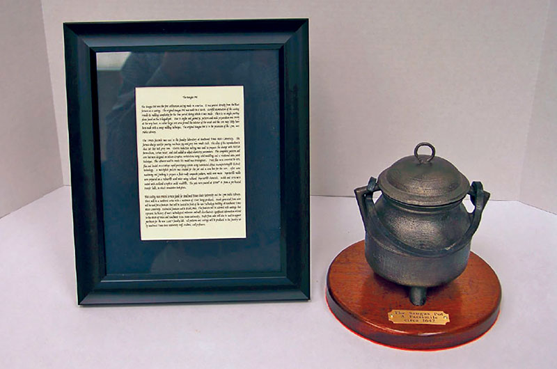
After pouring and shakeout, the project was ready for finishing. Figure 10 shows the final results—a successful facsimile of the original Saugus Pot, produced via modern molding methods.